20+ gateway network diagram
Shows interactions between two or more processes using more than one pool. Kubernetes Gateway API Concepts.

Community Gns3
After a network statement with mask is configured the show run command shows output similar to this.

. The default address of the NatNetwork is 1002024. Public Default Instances in private subnets can connect to the internet through a public NAT gateway but cannot receive unsolicited inbound connections from the internet. In the above diagram the HTTPRoute is splitting the traffic 9010 and sending.
While a traditional network is comprised of desktop computers modern networks may include laptops tablets smartphones televisions gaming consoles smart appliances and other. A data connection is initiated on port number 20. Learn more and find your nearest distributor.
An implementer is free to combine two functions in one node or to split a single function into two or more nodes. This page describes concepts related to Google Cloud VPN. Proxy ARP is defined in RFC 1027.
For these exercises the focus is on the network hosted on the ESXi and represented by the following three networks. Traffic from your VPC to Amazon S3 or DynamoDB is routed to the gateway endpoint. Cloud VPN securely connects your peer network to your Virtual Private Cloud VPC network through an IPsec VPN connection.
This layer defines how the data should be sent physically through the network. Each subnet route table must have a route that sends traffic destined for the service to the gateway endpoint using the prefix list for the service. Each of the functions in the diagram is explained below.
All combinations of pools processes and choreography may be used in a collaboration diagram. The following diagram shows a gateway that terminates inbound SSL connections. Traffic traveling between the two networks is encrypted by one VPN gateway and then decrypted by.
A network statement with mask 2552552550 needs to be configured to make it work. Use the Actisense USG-2 USB gateway to connect your PC to a marine standard NMEA 0183 data bus. A network consists of multiple devices that communicate with one another.
It can be as small as two computers or as large as billions of devices. Istios traffic routing rules let you easily control the flow of traffic and API calls between services. You create a public NAT gateway in a public subnet and must associate an elastic IP address with the NAT gateway at.
Istio simplifies configuration of service-level properties like circuit breakers timeouts and retries and makes it easy to set up important tasks like AB testing canary rollouts and staged rollouts with percentage-based traffic splits. This network does not fall on the boundary of a Class B network 25525500. When you create a NAT gateway you specify one of the following connectivity types.
A function is not a node hardware box. The SIG-Network community has come up with the following design goals for Gateway API to improve upon the Ingress resource. A network layer is a combination of the data line and defined in the article of OSI reference model.
Routing which you can combine with AB or canary strategies to achieve complex rollouts in a simple way. Below you can find the architecture diagram used for this. The mobile device sends the URL encoded request via network to a WAP gateway using WAP protocol.
The WAP gateway translates this WAP request into a conventional HTTP URL request and sends it over the internet. It shows a group of related message exchanges in a business. Simple Network Management Protocol SNMP is an Internet Standard protocol for collecting and organizing information about managed devices on IP networks and for modifying that information to change device behaviour.
Proxy ARP can help machines on a subnet reach remote subnets without the need to configure routing or a default gateway. For example if you create a new virtual network for the NAT Network mode in VirtualBox and set the 19216822024 network address the IP address of the gateway in this network will be 192168221. This layer is responsible for the transmission of the data between two devices on the same network.
You wish to move the responsibility for issues such as network security throttling or other network boundary concerns to a more specialized team. It requests data on behalf of the original requestor from any HTTP server upstream of the gateway. The Host A 1721610100 on Subnet A needs to send packets to Host D 1721620200 on Subnet B.
Here are some Frequently Asked Questions about the USG-2. Devices that typically support SNMP include cable modems routers switches servers workstations printers and more. The request reaches to a specified Web server and it processes the request just as it would have processed any other request and sends.
Difference between Border Gateway Protocol BGP. Efficiency is more in FTP. At the bottom of the diagram is the vApp network required to support the environment.
The following diagram shows how instances access Amazon S3 and DynamoDB through a gateway endpoint. Differences between OSI and TCPIP models. File sharing also comes in the category of advantages of FTP in this between two machines files can be shared on the network.
As shown in the diagram Host A has a 16 subnet mask. Access to the administration console goes through Unified Access Gateway port 9443 and IP 172168020 in this example associated with. For definitions of terms used in Cloud VPN documentation see Key terms.
The default gateway IP is 10021 the xxx1 template is used to assign the default gateway IP. R101show run begin bgp router bgp 1 network 17216100 mask 2552552550. 5 Application Gateway v2 SKU up and running Standard or WAF If you dont have an Application Gateway you can follow the step-by-step guide and create one here.
FTP sends the control information out-of-band as it uses a separate control connection. You need a private pfx certificate for your custom domain so you can upload it to the Application Gateway listeners. In general this is a simplified version of a collaboration diagram.
No firmware which means no configuration needed. The IP multimedia core network subsystem is a collection of different functions linked by standardized interfaces which grouped form one IMS administrative network.

Star Topology A 10 Nodes B 20 Nodes C 30 Nodes D 40 Nodes Download Scientific Diagram
![]()
Network Os Solutions For Carriers Service Providers Ip Infusion

A Simple Network Topology Diagram On The Left And Its Matching Download Scientific Diagram

4 The International 10 20 Standard Fp1 Measurement Position Relevant Download Scientific Diagram
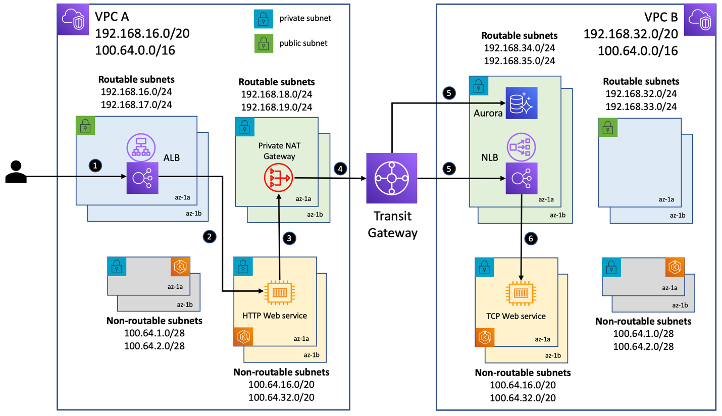
Addressing Ipv4 Address Exhaustion In Amazon Eks Clusters Using Private Nat Gateways Containers

Linear Topology A 10 Nodes B 20 Nodes C 30 Nodes D 40 Nodes Download Scientific Diagram

20 A Wide Area Network Download Scientific Diagram

Simplified Ims Network Architecture 18 Download Scientific Diagram

St Pancras Railway Station Map Station Map St Pancras St Pancras Station

Architecture Of 5g Cellular Network Download Scientific Diagram

Confidential Network Architecture And Security Requirements Download Scientific Diagram

Netgear Wifi Router Dual Band Wireless Speed Up To 1200 Mbps Up To 1200 Sq Ft Coverage 20 Devices 4 X 10 100 Fast Ethernet And 1 X 2 0 Usb Ports R6120 100cns Amazon Ca Electronics

Satellite Communication Network Diagram As Shown In The Figure The Download Scientific Diagram

Network Configuration For A Home Network With Three Different Traffic Download Scientific Diagram

Mpls Vpn Network 20 Download Scientific Diagram
Lora Architecture 20 Download Scientific Diagram

Addressing Ipv4 Address Exhaustion In Amazon Eks Clusters Using Private Nat Gateways Containers